


2D Contexts
This page has been automatically translated using the Google Translate API services. We are working on improving texts. Thank you for your understanding and patience.
Header
#include <draw2d/dctx.h>
Functions
| DCtx* | dctx_bitmap (...) |
| Image* | dctx_image (...) |
| void | draw_clear (...) |
| void | draw_matrix (...) |
| void | draw_matrix_cartesian (...) |
| void | draw_antialias (...) |
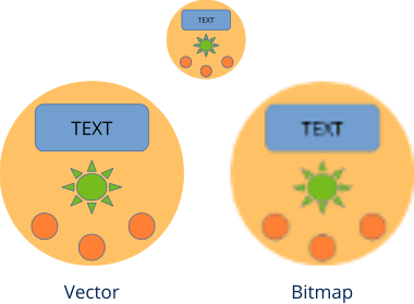
Vector graphics are composed of basic primitives such as lines, circles, text, etc, using the painter's algorithm (Figure 1): Incoming operations overlap existing ones. The result is stored in an intermediate buffer known as canvas or surface. This drawing surface is part of an object called context that also maintains certain parameters related to the appearance of primitives: Colors, line attributes, reference system, gradients, etc..
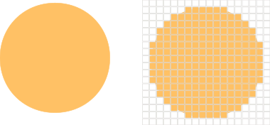
One of the advantages of working with parametric shapes is that image scaling can be done without loss of quality (Figure 2). This is because the conversion to pixels, a process called rasterization (Figure 3), is done in real time and constantly adjusts to the change of vectors. In bitmap images, an increase in size has associated a loss of quality.
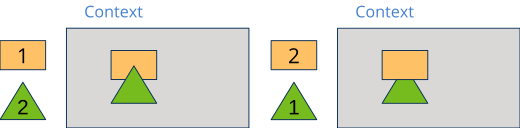
Draw2D allows working with two types of 2D contexts (Figure 4).
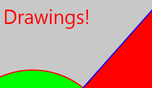
- Window context. The destination will be an area within a user interface window managed by a View control. This control maintains its own drawing context and sends it "ready to use" through the EvDraw event (Listing 1).
- Image context. Here the drawing commands will be directly dumped into memory to subsequently obtain an image with the final result (Listing 2).
1 2 3 4 5 6 7 8 9 10 11 12 13 14 |
static void i_OnDraw(App *app, Event *e) { const EvDraw *p = event_params(e, EvDraw); draw_clear(p->ctx, color_rgb(200, 200, 200)); draw_fill_color(p->ctx, color_rgb(0, 128, 0)); draw_rect(p->ctx, ekFILL, 100, 100, 200, 100); draw_fill_color(p->ctx, color_rgb(0, 0, 255)); draw_circle(p->ctx, ekFILL, 450, 150, 75); } View *view = view_create(); view_size(view, s2df(600, 400)); view_OnDraw(view, listener(app, i_OnDraw, App)); |
1 2 3 4 5 6 7 8 9 10 11 12 13 14 15 |
static i_draw(void) { Image *image = NULL; DCtx *ctx = dctx_bitmap(600, 400, ekRGBA32); draw_clear(ctx, color_rgb(200, 200, 200)); draw_fill_color(ctx, color_rgb(0, 128, 0)); draw_rect(ctx, ekFILL, 100, 100, 200, 100); draw_fill_color(ctx, color_rgb(0, 0, 255)); draw_circle(ctx, ekFILL, 450, 150, 75); image = dctx_image(&ctx); image_to_file(image, "drawing.png", NULL); image_destroy(&image); } |

As we can see, the drawing itself is done in the same way, the only thing that changes is how we obtained the context (DCtx). This allows us to write generic graphic routines without worrying about the destination of the final result. In the example DrawImg you have a practical step-by-step development of the use of contexts. The images that accompany the rest of the chapter have been obtained from this application.
Because it is not necessary to have a window to draw, Draw2d can be used in console applications to compose or edit images in an automated way.
1. Reference systems
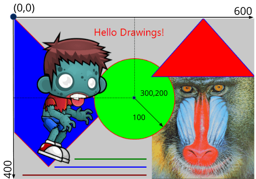
The drawing origin of coordinates is located in the upper left corner (Figure 5). The positive X move to the left and the positive Y down. Units are measured in pixels (or points in Retina displays). For example, the command:
1 |
draw_circle(ctx, ekSKFILL, 300, 200, 100); |
will draw a circle of 100 pixel radius whose center is 300 pixels to the left and 200 pixels down from the origin. This initial system is called identity since it has not yet been manipulated, as we will see below.
Although the initial scale is in pixels, we must banish the idea that we are directly manipulating pixels when drawing. Drawing contexts use floating point coordinates. For example, drawing a line between the points (0.23, 1.432) and (-45.29, 12.6756) is perfectly valid. Transformations and antialiasing may slightly alter the position or thickness of certain lines. Nor should we expect "identical" pixel-level results when migrating applications to different platforms, since each system uses its own rasterization algorithms. We must think that we are drawing on the real plane. To directly manipulate the pixels of an image, see image_pixels and image_from_pixels.
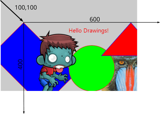
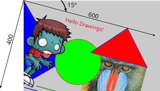
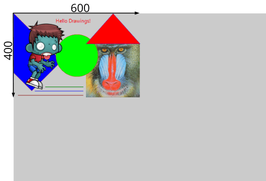
This initial reference system can be manipulated by 2D Transformations. The most common transformations in graphics are: Translations (Figure 6), Rotations (Figure 7) and Scaling (Figure 8).
- draw_matrixf will change the context reference system.
1 2 3 4 |
T2Df t2d; t2d_movef(&t2d, kT2D_IDENTf, 100, 100); draw_matrixf(ctx, &t2d); i_draw(...); |
1 2 3 4 |
T2Df t2d; t2d_rotatef(&t2d, kT2D_IDENTf, 15 * kBMATH_DEG2RADf); draw_matrixf(ctx, &t2d); i_draw(...); |
1 2 3 4 |
T2Df t2d; t2d_scalef(&t2d, kT2D_IDENTf, .5f, .5f); draw_matrixf(ctx, &t2d); i_draw(...); |
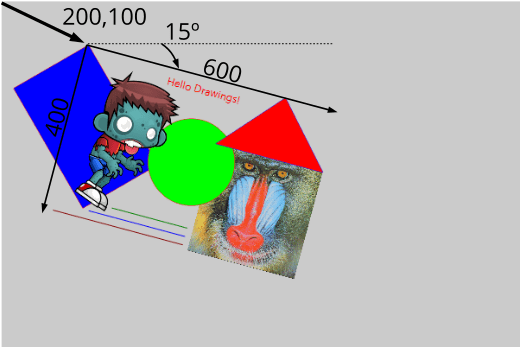
The transformations can be accumulated, but we must bear in mind that they are not commutative operations, but that the order in which they are applied will influence the final result. For example in (Figure 9) we observe that the drawing has moved (100, 50) pixels, instead of (200, 100), because the translation is affected by previous scaling. More details at Composition of transformations.
1 2 3 4 5 6 |
T2Df t2d; t2d_scalef(&t2d, kT2D_IDENTf, .5f, .5f); t2d_movef(&t2d, &t2d, 200, 100); t2d_rotatef(&t2d, &t2d, 15 * kBMATH_DEG2RADf); draw_matrixf(ctx, &t2d); i_draw(...); |
1.1. Cartesian systems
There is a dichotomy when drawing in 2D: On the one hand, traditionally desktop systems and digital images place the origin of coordinates in the upper left corner with the Y axis growing down (Figure 10). On the other hand, the Cartesian systems used in geometry place it in the lower left corner, with Y growing up. This creates a dilemma about whether one system is better than another.
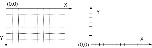
The answer is clearly no. Even in the same drawing, we may need to combine both depending on the element we are treating. For texts and images, the screen system is more intuitive since it reproduces the paper or canvas of the physical world. For mathematical functions, bar graphs, plans and other aspects related to the technical world, the Cartesian is much more comfortable and natural.
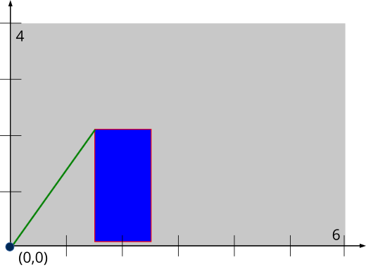
- draw_matrix_cartesianf set the context reference system in Cartesian coordinates. In (Figure 11) we have used a 6x4 unit Cartesian system mapped onto a 600x400 pixel window.
1 2 3 4 5 6 7 8 9 |
T2Df t2d; draw_line_color(ctx, color_rgb(255, 0, 0)); draw_line_width(ctx, .03); draw_fill_color(ctx, color_rgb(0, 0, 255)); t2d_scalef(&t2d, kT2D_IDENTf, 100, 100); draw_matrix_cartesianf(ctx, &t2d); draw_rect(ctx, ekSKFILL, 1.5f, .1f, 1, 2); draw_line_color(ctx, color_rgb(0, 128, 0)); draw_line(ctx, 0, 0, 1.5f, 2.1f); |
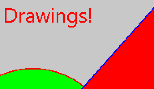
2. Antialiasing
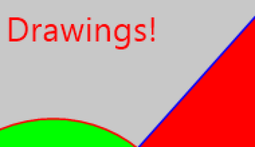
Given the discrete nature of monitors and digital images, a staggered effect (sawtooth) is produced by transforming vector primitives to pixels (Figure 12). This effect becomes less noticeable as the resolution of the image increases, but still the "pixelated" remains patent. The antialiasing, is a technique that reduces this step effect by slightly varying the colors of the pixels in the environment near the lines and contours (Figure 13). With this, the human eye can be deceived by blurring the edges and generating images of greater visual quality. In return we have the cost in the performance of applying it, although for years that the calculations related to antialiasing are made directly in hardware (Figure 14), so the impact will be minimal.
- draw_antialias allows to activate or deactivate the antialiasing calculations.
3. Retina displays
At the end of 2014 Apple introduced its news iMac with high resolution Retina Display (5120x2880). Normally, these monitors work in scaled mode (2560x1440) allowing double density pixels (Figure 15). Apple differentiates between points on the screen, which are what really manipulates the application and physical pixels. Therefore, our 600x400 window will really have 1200x800 pixels on Retina computers, although the application will still "see" only 600x400 points. The operating system converts transparently. In fact, we don't have to do anything to adapt our code, since it will work in the same way on both normal iMac and those equipped with Retina monitors.
This double density will be used by the rasterizer to generate higher quality images by having more pixels in the same screen area. In (Figure 16) and (Figure 17) we see the extra quality that these models provide.

dctx_bitmap ()
Create a memory context, in order to generate an image.
DCtx*
dctx_bitmap(const uint32_t width,
            const uint32_t height,
            const pixformat_t format);
| width | Image width in pixels. |
| height | Image height in pixels. |
| format | Pixel format of the generated image. |
Return
Drawing context.
Remarks
When we finish drawing, we must call dctx_image to get the picture.
dctx_image ()
Get the result image after drawing in the context created with dctx_bitmap.
Image*
dctx_image(DCtx **ctx);
| ctx | The context, which will be destroyed after generating the image. |
Return
The image.
draw_clear ()
Clears the entire context area, using a solid color.
void
draw_clear(DCtx *ctx,
           const color_t color);
| ctx | Drawing context. |
| color | Background color. |
draw_matrix ()
Set the context reference system (affine transformation).
void
draw_matrixf(DCtx *ctx,
             const T2Df *t2d);

void
draw_matrixd(DCtx *ctx,
             const T2Dd *t2d);

void
Draw::matrix(DCtx *ctx,
             const T2D *t2d);
| ctx | Drawing context. |
| t2d | Transformation. |
Remarks
The origin of coordinates is in the upper left corner. The Y axis increases down.
draw_matrix_cartesian ()
Set the reference system in Cartesian coordinates.
void
draw_matrix_cartesianf(DCtx *ctx,
                       const T2Df *t2d);

void
draw_matrix_cartesiand(DCtx *ctx,
                       const T2Dd *t2d);

void
Draw::matrix_cartesian(DCtx *ctx,
                       const T2D *t2d);
| ctx | Drawing context. |
| t2d | Transformation. |
Remarks
The origin of coordinates is in the lower left corner. The Y axis increases upwards. See Cartesian systems.
draw_antialias ()
Enable or disable antialiasing.
void
draw_antialias(DCtx *ctx,
               const bool_t on);
| ctx | Drawing context. |
| on |
|
Remarks
The antialias can change in each primitive. It is not necessary to establish a policy for the whole drawing. See Antialiasing.